Working with Concrete
A Safe and Easy Material
Concrete is easy to work with, versatile, durable, and economical. It is also one of the safest building materials available, with a few common-sense precautions.
Here are some pointers for how to work with concrete to get the best results in the safest way.
Placing and Finishing Concrete
-
Mix and handle concrete in a time-sensitive way in coordination with transporting, placing, and finishing it. Deposit the material only as fast as it can be handled, and as close as possible to its final position.
-
In slab construction, start placing your concrete along the perimeter at one end of the work with each batch placed against previously dispatched concrete.
- Do not dump the concrete in separate piles and then level and work them together.
- Do not deposit the concrete in large piles and move it horizontally into final position.
-
Compacting fresh concrete to mold it into forms is called consolidation. In some types of construction, concrete is placed in forms and then consolidated. Consolidation compacts fresh concrete to mold it within the forms and around embedded items and reinforcement. Consolidating concrete also eliminates stone pockets, honeycomb, and entrapped air.
-
The most widely used method for consolidating concrete is vibration, either internal or external. When you vibrate the concrete, it temporarily destroys the internal friction between the aggregate particles, causing the concrete to behave like a liquid. It settles in the forms, and the large entrapped air voids rise more easily to the surface.
-
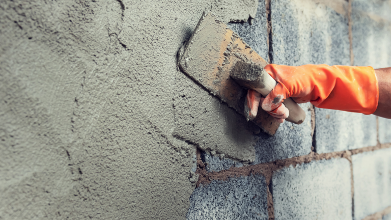
Finish concrete that will be visible on driveways, highways, or patios. Choose among colors and textures, including patterned-stamped surfaces.
-
Screeding or strikeoff is the process of cutting off excess concrete to bring the top surface of the slab to proper grade. The process: Move a straight edge across the concrete with a sawing motion and advance it forward a short distance with each movement.
-
After strikeoff, use a bull float—a long-handled straight edge that you pull across the concrete—to eliminate high and low spots and embed large aggregate particles immediately.
-
Jointing eliminates unsightly random cracks. Make contraction joints with a hand groover or by inserting strips of plastic, wood, metal, or preformed joint material into the unhardened concrete. You can make sawcut joints after the concrete is hard or strong enough to prevent raveling.
-
After jointing the concrete, you should float it with a wood or metal hand float or a finishing machine using float blades. This embeds aggregate particles just beneath the surface. It also removes slight imperfections, humps, and voids and compacts the mortar at the surface in preparation for additional finishing operations.
-
If you want a smooth, hard, dense surface, trowel your surface after floating it using a steel trowel. (Always trowel a previously floated surface; troweling after only bull floating is not an adequate finish procedure.)
-
You can produce a slip-resistant surface by brooming before the concrete has thoroughly hardened—but it should be sufficiently hard to retain the scoring impression.
Working with Air-Entrained Concrete
Air-entrained concrete contains billions of microscopic air cells per cubic foot. These air pockets relieve internal pressure on the concrete by providing tiny chambers for water to expand into when it freezes.
Air-entrained concrete is produced using air-entraining portland cement or by introducing air-entraining agents. This should be done under careful engineering supervision while the concrete is mixed on the job. The amount of entrained air is usually between 4 and 7%of the volume of the concrete but may be varied as required by special conditions.
Working Safely with Concrete
How to Reduce Risk
Concrete is rarely harmful to workers on the job site. Simply take proper precautions during mixing, handling, and finishing. Review these common-sense tips to stay safe, prevent injuries.
-
- Wear waterproof gloves, a long-sleeved shirt, and long pants to work.
- If your clothing soaks up moisture from fresh concrete, rinse it promptly to avoid alkaline and other irritants touching your skin.
- High rubber boots can protect your legs and feet if you must stand in fresh concrete while it is placed, screeded, or floated.
- Use waterproof pads between knees, elbows, or hands and any fresh concrete surfaces while performing finishing tasks.
-
- While you’re working on any job site, wear a hard hat or safety hat to protect you from the potential hazards of construction equipment and tools.
- Use full-coverage goggles or safety glasses with side shields to protect your eyes against dust, splattering concrete, and foreign objects.
- Flush your eyes with clean water if they come in contact with fresh concrete.
-
- Prolonged contact between fresh concrete and skin surfaces, eyes, and clothing can result in severe and even third-degree burns. Avoid skin irritation by washing frequently with pH-neutral soap and clean water.
- Consult a physician if irritation persists and seek medical attention for deep burns or large affected areas.
Need to Knows
- Concrete is abrasive: Sand in fresh concrete is rough on bare skin.
- Portland cement can burn you because it is alkaline in nature.
- Cement mixtures are caustic. Concrete and other cement mixtures can have pH levels of 12 to 13. Strong bases, just like strong acids, can harm skin.
- Portland cement is hygroscopic—it absorbs water. In fact, it needs water to harden and will draw moisture away from anything it contacts, including skin.
-
Concrete and the materials it’s composed of are heavy, even in small quantities. Place them as close as possible to the concrete’s final position to minimize effort and risk.
Lifting Cement Materials
- Lifting these materials correctly can help protect your back from injury:
- Keep your back straight, legs bent, and the weight between your legs as close to your body as possible.
- Do not twist at the waist while lifting or carrying these items.
- Rather than straining your back with a heavy load, get help.
- Push—don’t lift—into final position with a shovel with a shovel after it’s been deposited. A short-handled, square-end shovel is a good tool for spreading concrete. You can also use special concrete rakes or come-alongs.
-
- These resources provide valuable safety information:
The American Society for Concrete Construction (ASCC); call 800-877-2753. - The ASCC Safety Manual
- The Occupational Safety and Health Administration has guidelines on concrete product and worksite safety.
- Read cement manufacturers’ material safety data sheets for products and ingredients.
- These resources provide valuable safety information: